SimonD’s workbench

mickoo

Western Thunderer
indeed, we have already had the discussion when @Nick Dunhill was building a model based on an Ace kits scrapbox.
I'm reasonably sure it wasn't ACE, they don't do 3D in their kits, it was 88D I think and I was asked to do replacements for some parts.

That's not to say Ace don't have their issues, but poor 3D is not one of them :))
 

simond

Western Thunderer
in my comment referring to Nick & Ace kits, I was thinking of ”not very good etched kits” rather than 3DP, sorry if I wasn’t clear enough, this was where my mind was;

Post in thread 'Nick Dunhill's workbench - Scratchbuilding a Reid NBR Atlantic from an ACE Kit.'
Nick Dunhill's workbench - Scratchbuilding a Reid NBR Atlantic from an ACE Kit.

and specifically this stonking quote…

“If you really feel your life would be incomplete without a NBR Reid Atlantic, and there's no doubt it's a handsome loco, I would urge you not to buy this kit under any circumstances. It is a very very poor product and ought not to be on the market. Even if you're pretty handy at modifying kits, spend the £225 on gin and fags and scratchbuild one instead.”
 
Last edited:

simond

Western Thunderer
Anyway, back to the workbench:

The cat’s on the back of the sofa, the el cheapo CNC miller is earning its keep, bogie slide for the Manor & slide bars for 13xx‘s.
I’m about to break out the lathe to make a bogie pivot bush for the Manor, and the Saturn is printing another N6.
 

Clarence3815

Western Thunderer
One of my other hobbies is fairground machines and models thereof. Currently I have on the bench an almost complete scenic railway. This is a machine whose track is about forty feet in diameter and the basic ride consists of a circular trip around the track with two hills and two dales per revolution. The model is about 1/16 scale and sits nicely on a board 48 inches wide. The real machine runs between 8-10 rpm and the model will do about 13.5rpm happily.

What has this to do with 3D printing????

Well. The real machine breaks down into nine loads for transport and the model does as well. Apart from fixings there about 800 parts. The track itself is made up of 18 elements per circle and there are three complete circles, so 54 parts. There are also electrical pickup rails but they only extend over 5/9ths of the circle so another 20 elements and 74 parts in total. These have all been 3D printed by a friend from the Meccano world (another hobby)! I don`t know what his machine is or the material he uses.

I tried to make these elements in several ways but none satisfied. I don`t know how many of you can 3D visualise this but I`ll try to explain.


The track consists of two repeats so nine individual elements for each repeat. The track is inclined four degrees towards the centre. The radius is the same for each element. The elements rise about 2.75 inches in total and the rail follows a sine wave form approximately. When I spoke to my Meccano friend he said he could print them and he did. Each of the running rails has a steel plate on top and the electrical ones have copper plates. These are held in place by 10BA bolts just screwed in place (no nuts underneath). The machine has run about forty hours to date whilst I finalise details ready for delivery to my customer. The printed elements show no signs of distress, took the bolts happily and have been assembled and re-assembled about 15 times in total. I know they are not completely solid but I don`t know what percentage the voids comprise.

I am not aware of any other model to this scale in the model fairground world using 3D parts for the track elements of a ride. Several people are using decorative 3D parts.


I`d like to think Mickoo would think I`ve taken a leap of courage to try this method.

I also have 3D printed tyres to 1/16 scale which `squidge` to my satisfaction. But that is another story.

Bernard
 

simond

Western Thunderer
ANOTHER N6?
Whole herd of them…. Well, four. Nick noticed an omission which has now been corrected. The aim is to have four good ones!

I’m beginning to develop a bit of a 3D queue…

Theres a queue on the CAD too, I normally have a bit of a go at model CAD at lunchtime at work, but been a bit busy lately, so not quite as motivated as normal. It’ll settle down in a few days and I can get on.

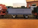
Hopefully, 200 buffers are coming my way over the weekend, which will enable a bit of progress on a few other wagons that have been gracing the back & front sidings at PD. That’ll be nice.
 

Clarence3815

Western Thunderer
I`m happy to do that but I think I should clear it with my client first that he is happy for that to be done. There are a number of people waiting for pictures (several from WT) and I feel I should wait until the machine is delivered, up and running.

Bernard
 

Dog Star

Western Thunderer
Hopefully, 200 buffers are coming my way over the weekend...
I have a need for about 100 GWR wagon buffer heads/rams.... and I have done research on what is available from the usual suppliers. At the moment I have just one option and the price is eye-watering at over £1 per buffer - please, what is your source and cost?

regards, Graham
 

simond

Western Thunderer
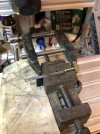
Progress has not been glacial…. However the slidebars are ready for a little trimming: they require approximately 0.5mm removing from each side for a length of 16.3m and rather than file it I felt that machining is called for.

The el cheapo miller is set up to do the deed. Much faffing ensured that I was not able to do any actual metal cutting before MrsD returned, so maybe tomorrow. If I can get one done to my satisfaction, without breaking a cutter, then it’ll be a doddle to do the remaining 5 (two locos remember).

image.jpg

Of course, if it all goes pear shaped, there will be all sorts of very naughty words. Let’s hope that if that is the case, the damage is restricted to the cutter and the workpiece survives - I can order, but do not have, spares.

Next steps will be to counterbore the coupling rods for the recessed crankpin. Still not decided how best to do that. The counterbore should be easy; ensuring it’s concentric with the existing hole is the difficult bit!

And then I’m going to try to use the el cheapo to make the coupling & connecting rods for the Manor, which is low risk, as I can always get them laser cut, or buy some of Billy’s. I’m going to use steel, because it’s strong enough, cheaper than brass or NS, and looks like steel.

image.jpg

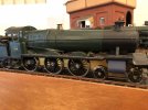
I also got a prototype of the N6 on its wheels using Ambis axle guards with springing. They are a bit of a faff to assemble. Rides beautifully but looks too high to me.

at both ends :)

image.jpg

Further investigation required!
 

Dave Holt

Western Thunderer
Simon.
Can you not set up the front rods under your milling machine and use the shank on a suitable sized drill, held in the chuck, as a mandrel to centre the milling head over the existing crank-pin sized hole. When happy, lock everything up, swap to the counter bore sized flat ended drill, clot drill, etc., and machine the counterbore to the required depth?
Dave.
 

simond

Western Thunderer
Simon.
Can you not set up the front rods under your milling machine and use the shank on a suitable sized drill, held in the chuck, as a mandrel to centre the milling head over the existing crank-pin sized hole. When happy, lock everything up, swap to the counter bore sized flat ended drill, clot drill, etc., and machine the counterbore to the required depth?
Dave.
Thanks Dave, that is one of the options. Set the miller to a known location with a snug fitting drill located in the rod, clamp the rod in place, and work from there. I’ll do a helical cut with a very small cutter, eg 1 or 1.2mm, as that will put far lower loads on everything than a counterbore sized (eg 3.5 or 4 dia) drill would do.

The miller is a GRBL driven thing and has the “touch” probe function, which I have not yet experimented with, this would allow me fix the rod, and then work out where it is. I guess the mirror approach to the first.

I think I need to get that sussed and then decide which way to go before attacking Chris’ rods.

ta
Simon
 

simond

Western Thunderer
Well, I am peeved. I set to, to do the slidebars before 'erself's train gets in, and it did not quite go according to plan, but no damage done, so on with the job... except, the damn miller motor drive has packed up again :( Unfortunately, I haven't yet got the first one fixed, so now I have two GRBL controllers that are hors service :( This is more than a bit of a PITA as it prevents progress on the panniers and the manor. I shall have to order some suitable MOSFETs and practice my soldering.

It is either the el cheapo miller's motor that is a bit demanding, or some bizarre glitch. I'm sure that this is not expected. Given there is no speed control (there is a PWM output, so perhaps I should...) I cannot imagine why it packs up like this. Damn irritating. :rant: I shall go and put the bins out and the dinner on.
 

simond

Western Thunderer
Thanks Dave, that is one of the options. Set the miller to a known location with a snug fitting drill located in the rod, clamp the rod in place, and work from there. I’ll do a helical cut with a very small cutter, eg 1 or 1.2mm, as that will put far lower loads on everything than a counterbore sized (eg 3.5 or 4 dia) drill would do.

The miller is a GRBL driven thing and has the “touch” probe function, which I have not yet experimented with, this would allow me fix the rod, and then work out where it is. I guess the mirror approach to the first.

I think I need to get that sussed and then decide which way to go before attacking Chris’ rods.

ta
Simon

I spoke to our Production Manager today, he knows a thing or two about CNC machining, and his recommendation is plan A, ie, locate the part on a suitable block, by means of a dowel (or drill) at a known position on the milling table, and then clamp it. Remove dowel/drill, replace with suitable cutter, helically mill counterbore about known axis position.

once I’ve fixed the milling machine…
 

Pencarrow

Western Thunderer
Well, I am peeved. I set to, to do the slidebars before 'erself's train gets in, and it did not quite go according to plan, but no damage done, so on with the job... except, the damn miller motor drive has packed up again :( Unfortunately, I haven't yet got the first one fixed, so now I have two GRBL controllers that are hors service :( This is more than a bit of a PITA as it prevents progress on the panniers and the manor. I shall have to order some suitable MOSFETs and practice my soldering.

It is either the el cheapo miller's motor that is a bit demanding, or some bizarre glitch. I'm sure that this is not expected. Given there is no speed control (there is a PWM output, so perhaps I should...) I cannot imagine why it packs up like this. Damn irritating. :rant: I shall go and put the bins out and the dinner on.

Would sir like a suitable serving of swear words?
 
Top