have you made any options for the laser cutting of the sleepers as there was a bit of processing required to laser cut templot plans?
Hi Phil,
Which Templot plans are you referring to? The Plug Track has been in an experimental state for a year or two now, you need to refer to Templot Club to see the latest details. There is an adjustable laser-kerf line around the timber outlines and chair sockets -- see item 2. below:
With the
experimental chairing switched on, this is the additional detail which you see on the trackpad when zoomed-in:
1. timber outline.
2. black lines -- cutter kerf line for laser cutters. Outside the timbers, inside the sockets.
3. extent of the timber flanges.
4. chair base outline.
5. chair base corner radius.
6. socket outline. The default size is derived from the centres of the base corner radii.
For REA S1 chairs, that's 6" wide x 12.5" long.
For REA L1 chairs, that's 7.5" wide x 7" long. L1 chairs are not used on 10" wide sleepers.
7. chair plug outline at the top. There is a small clearance from the socket on the sides, and a smaller clearance at the ends.
8. outline of the chair plug at the bottom inset section.
9. plug corner relief angles. Small for FDM and laser-cut sockets. Larger for CNC milled sockets.
10. outline of the top of the support pyramid below the plug.
11. outline of the bottom of the support pyramid.
12. chair screw/bolt centres.
All the above can be adjusted via the buttons on the DXF export dialog (except 4, 5, 12). They are shown on the trackpad so that you can see the effect of any changes (after rebuilding the templates). The chair dimensions 4, 5, 12, are set in the custom chairs dialog (not yet done).
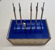
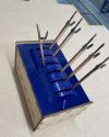
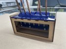
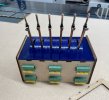
Steve Cornford is using a 2-layer system with a laser-cut sub-base and locator plugs for the timbers (there is an option for those in Templot), see his post:
Experimental Plug Track: 3D-printed, CNC-milled, laser-cut
cheers,
Martin.


