You are using an out of date browser. It may not display this or other websites correctly.
You should upgrade or use an alternative browser.
You should upgrade or use an alternative browser.


simond
Western Thunderer
Just been on line looking for wagon wheels as I have quite a few to build.
Slaters now advertise their 7mm FS spoked wagon wheels at £11.50 per wagon. Hoping to get a deal (I’m going to buy twenty sets) I went on eBay, and was amused & perplexed in roughly equal measure to find that you can buy them for prices from fifteen quid and up.
who’s buying this stuff?
Slaters now advertise their 7mm FS spoked wagon wheels at £11.50 per wagon. Hoping to get a deal (I’m going to buy twenty sets) I went on eBay, and was amused & perplexed in roughly equal measure to find that you can buy them for prices from fifteen quid and up.
who’s buying this stuff?
Allen M
Western Thunderer
Those who assume that if it's on ebay it must be a bargain.who’s buying this stuff?
Regards
Allen
Bill Campbell
Western Thunderer
Hi Simon
Prices seem to have jumped over the last 6 months - a set of 4 3-hole wagon wheels and bearings I bought for £8.70 are now priced at £9.90. These were from Invertrain and are a long way from being the most expensive on the market - have a look at:
One of the things to be really careful about is retailers advertising items at more then the manufacturers list price!
Regards.
Last edited:
Bill Campbell
Western Thunderer
The wheels Chris sells are usually those from Haywood. They are a little finer than Slaters and they are already blackened.Thanks Bill, good call!
I’ll give Chris a ring in a day or so.
cheers
Simon
Regards.
simond
Western Thunderer

I think I’ll add a lick of rusty paint and call it a wrap. Really pleased with this model, it’s been great fun to sort out, and I think looks rather nice.
The chassis is sprung, using an 8 thou guitar E string, as previously shown. I also 3DP’d the brakes and the v hangers and brake lever. Pending finding a drawing or better info about the prototype, it has single sided brakes (to RCH 1923 drawings, released only 20 years after the wagon was built, assuming my data is pukka). As noted previously, this approach will work for Parkside wagons.
I found this link which describes what I believe to be the prototype, same number series and size tallies pretty well.
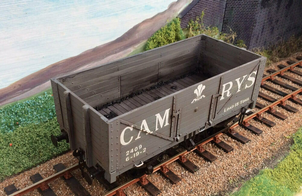
Cambrian Railways/GW 15ton Coal Wagon
In 1903, the Cambrian Railways purchased 50 15ton coal wagons from Messrs. Pickering. As a step forward, this was nothing short of amazing, as 2 plank wagons rated at 8tons were being bought at the same time! It has not been possible yet to establish the reasons for these very large wagons, but...
 taffvalemodels.ecwid.com
My wagon is 122mm long in the body, scales to 17’5”, and 58mm wide, 8’3” or thereabouts. Not grumbling too much
")
It still needs brake safety loops. I might print up a couple of solebar number & owner plates and glue them on. Half moon plates for the W irons? Where to stop?..
The Taff kit looks to build into a very nice model, but I’m sure could not have provided the fun (or learning opportunities) that this one has.
take-away lessons:
I didn’t know that RCH brake blocks had a “hook” that fits round the flange, presumably to stop them slipping down the coning. Yes, my models do too…
I also didn’t know that RCH brake pushrods were composite, iron/wood/iron. Every day’s a school day.
the external brake levers and v hangers are too thin & too fragile. I‘ll have to add a bit of thickness next time I print some.
the slotted rack for the brake lever closed up when printing, I’ll have to make it a bit stiffer and add some more supports
I didn’t allow enough clearance on the functional axleboxes, so had to spend some time filing. Easy fix in CAD. @Giles recommendation of pencil lead as a dry lubricant has been used.
I should probably cheat on the spring - axlebox clearance to save further filing.
100 micron “v” grooves between spring leaves are difficult to see. Try a little bit bigger.
Cheers
Simon
Last edited:

simond
Western Thunderer
Hi Kev,
each part is printed separately. Easiest way to explain is a picture…

the chassis has gone in two halves as the axleboxes are trapped by the retainers which are printed as part of the W irons. Because of this, the boxes go in from the top, which means that the ends of the W irons have to be connected by a stiff loop that goes around the back of the wheel. That pretty much drives the shape of the two chassis blocks.
There are 3 screw holes to retain the block to the wagon, but they could be glued, of course, and I put two transverse 2mm holes so I can use a bit of cocktail stick to pin the halves together, in alignment.
it would be possible to make the W irons open at the bottom, but then the retainer would need to be glued on. The axleboxes wouldn’t fall out because the spring wire retains them, so this would be possible. Might try it.
The axleboxes are printed with a pair of legs that rise up to solebar level behind the W iron, so they are pretty much invisible. On top of this, there is a lump through which the spring wire passes. These are more or less a 3DP version of the Exactoscale etched brass ones, iirc, though of course, I’ve moulded the axlebox as one piece, which eliminates the risk of gluing it all up solid. The axleboxes are printed with a 2.5mm hole for a Slaters bush, this needs a twiddle with a drill to clear it to diameter, and the bushes just push in.
The brake shoes, rocker, pushrods and inner V hanger are printed as one piece, I’ve only done one hand so far, but it’s easy to mirror for 4-shoe brakes (or not for single or either side, as required). The brake assy simply pushes into the slot in the chassis block, add a drop of cyano to fix. I will add the holes for the brake safety loops next time I print some.
Springs are also printed separately. I’ve done several, these are RCH pattern 3’6” for wooden solebars.
The funny bushes with two holes allow use of a single spring on the couplings. See pic in post 503. I’m not being stingy, it means the wagon is pulled along by the rearmost buffer beam in compression, rather than the front buffer beam being pulled off. It also effectively doubles the rate of the springs, which, when I’ve converted more stock will prevent the “strangled chicken” appearance when all the couplings are stretched beyond belief…. This seems to be a particular issue with RTR stock, Chinese springs are rather wimpish (Or, more likely, underspecified)
the outer V-hanger, lever and rack are also a separate print, as they fit the outside of the solebar. They need to be a bit thicker too, far too fragile at present.
The Saturn printer is fairly large, so I can get two wagons’ worth of bits on the build plate at one go, it takes just less than three hours to print, and the slicer reckons it uses about two quids’ worth of resin. That doesn’t allow for the wastage when clearing up, though.
hope that answers your question.
atb
Simon
each part is printed separately. Easiest way to explain is a picture…
the chassis has gone in two halves as the axleboxes are trapped by the retainers which are printed as part of the W irons. Because of this, the boxes go in from the top, which means that the ends of the W irons have to be connected by a stiff loop that goes around the back of the wheel. That pretty much drives the shape of the two chassis blocks.
There are 3 screw holes to retain the block to the wagon, but they could be glued, of course, and I put two transverse 2mm holes so I can use a bit of cocktail stick to pin the halves together, in alignment.
it would be possible to make the W irons open at the bottom, but then the retainer would need to be glued on. The axleboxes wouldn’t fall out because the spring wire retains them, so this would be possible. Might try it.
The axleboxes are printed with a pair of legs that rise up to solebar level behind the W iron, so they are pretty much invisible. On top of this, there is a lump through which the spring wire passes. These are more or less a 3DP version of the Exactoscale etched brass ones, iirc, though of course, I’ve moulded the axlebox as one piece, which eliminates the risk of gluing it all up solid. The axleboxes are printed with a 2.5mm hole for a Slaters bush, this needs a twiddle with a drill to clear it to diameter, and the bushes just push in.
The brake shoes, rocker, pushrods and inner V hanger are printed as one piece, I’ve only done one hand so far, but it’s easy to mirror for 4-shoe brakes (or not for single or either side, as required). The brake assy simply pushes into the slot in the chassis block, add a drop of cyano to fix. I will add the holes for the brake safety loops next time I print some.
Springs are also printed separately. I’ve done several, these are RCH pattern 3’6” for wooden solebars.
The funny bushes with two holes allow use of a single spring on the couplings. See pic in post 503. I’m not being stingy, it means the wagon is pulled along by the rearmost buffer beam in compression, rather than the front buffer beam being pulled off. It also effectively doubles the rate of the springs, which, when I’ve converted more stock will prevent the “strangled chicken” appearance when all the couplings are stretched beyond belief…. This seems to be a particular issue with RTR stock, Chinese springs are rather wimpish (Or, more likely, underspecified)
the outer V-hanger, lever and rack are also a separate print, as they fit the outside of the solebar. They need to be a bit thicker too, far too fragile at present.
The Saturn printer is fairly large, so I can get two wagons’ worth of bits on the build plate at one go, it takes just less than three hours to print, and the slicer reckons it uses about two quids’ worth of resin. That doesn’t allow for the wastage when clearing up, though.
hope that answers your question.
atb
Simon
simond
Western Thunderer
It’s at about this point in the game when it’s obvious that the smart money would have been on 3D printing the damn chassis too…
Still the discharge valves are fitted, and that’s a major step forward.

well, major…? Let’s say it’s been putting me off for a while.
Must fix that buffer stock. Doesn’t look that bad except through the cold, glass eye…
Still the discharge valves are fitted, and that’s a major step forward.
well, major…? Let’s say it’s been putting me off for a while.
Must fix that buffer stock. Doesn’t look that bad except through the cold, glass eye…
Simon
thanks for the comprehensive reply. I'm just working through some online tutorials for Fusion360 and reckon I'm not too far off attempting some drawings of my own. I'm quickly coming to the realisation that the drawings are only a small part of the process and trying to envisage the process in the steps required will take some planning.
When I'm comfortable with drawing I'll have a go at printing.
Kev
simond
Western Thunderer
Kev,
happy to have helped, do have a look at the 3D printing thread, there are many sage words from those much more experienced than I.
CAD. I’m an Engineer by profession, though a latecomer to 3D CAD. I’m reasonably proficient, though youngsters are both quicker and more knowledgeable/versatile. I trained in CREO/ ProE, and subsequently self-converted to Solidworks. I’m pretty confident that, given good data (and enough time!) I can model pretty much anything, so the CAD isn’t the stumbling block, but don’t underestimate the hours that it can consume.
I think the big road block is finding good data to model from. Clearly, there are drawings published in magazines & such, and the museums (York, Swindon, etc) and societies ( Didcot, etc) have drawings, and prototypes to measure and photograph, but it eats time, and depends on accessibility. Of course, given some leading dimensions, it’s relatively easy to take a flyer and guesstimate, but if your luck runs out, you’ll be frustrated with the result. Maybe I’m too cautious…. I guess you have to find a formula that works for you.
I found the process from CAD to print to be fairly pain-free, but choosing the angles to mount the models and slicing are black arts, and can make a massive difference to the outcome from the same 3D model, so that too is a learning curve, but so far I’ve only had a couple of disastrously total-fail prints, though I’ve have many where one part or another could have been (much) better. At least, doing a load of stuff, ideally from different bits of different projects, on the same print run, means that some things will be ok, even if others are a dog’s breakfast. Printing the same thing at different angles helps too. This avoids total gloom…
Start simple, a few chimney pots, an oil drum. I downloaded a couple of Clydesdale horses and a cow, and rescaled them. These are easy wins and give confidence.
go for it, it’s great fun!
happy to have helped, do have a look at the 3D printing thread, there are many sage words from those much more experienced than I.
3D Printing - whether to buy, what to buy and how to use it?
Following John Baker’s kind offer to 3D print the tanks for my model, I’m really intrigued by the process & possibilities. John uses an Elegoo printer, I’m interested to know what others have, what their impressions are, etc. I am seriously tempted! Also, the process, there seems to be a...
www.westernthunder.co.uk
CAD. I’m an Engineer by profession, though a latecomer to 3D CAD. I’m reasonably proficient, though youngsters are both quicker and more knowledgeable/versatile. I trained in CREO/ ProE, and subsequently self-converted to Solidworks. I’m pretty confident that, given good data (and enough time!) I can model pretty much anything, so the CAD isn’t the stumbling block, but don’t underestimate the hours that it can consume.
I think the big road block is finding good data to model from. Clearly, there are drawings published in magazines & such, and the museums (York, Swindon, etc) and societies ( Didcot, etc) have drawings, and prototypes to measure and photograph, but it eats time, and depends on accessibility. Of course, given some leading dimensions, it’s relatively easy to take a flyer and guesstimate, but if your luck runs out, you’ll be frustrated with the result. Maybe I’m too cautious…. I guess you have to find a formula that works for you.
I found the process from CAD to print to be fairly pain-free, but choosing the angles to mount the models and slicing are black arts, and can make a massive difference to the outcome from the same 3D model, so that too is a learning curve, but so far I’ve only had a couple of disastrously total-fail prints, though I’ve have many where one part or another could have been (much) better. At least, doing a load of stuff, ideally from different bits of different projects, on the same print run, means that some things will be ok, even if others are a dog’s breakfast. Printing the same thing at different angles helps too. This avoids total gloom…
Start simple, a few chimney pots, an oil drum. I downloaded a couple of Clydesdale horses and a cow, and rescaled them. These are easy wins and give confidence.
go for it, it’s great fun!
Last edited:
Clarence3815
Western Thunderer
Evening Simon,
What is the thinnest layer your printer can print?
What is the thinnest layer your printer can print?
simond
Western Thunderer
morning Bernard,
Almost see-through. 28 microns according to the spec.
Practically, I’m still using 50.
Much depends on orientation. Anything less than 100 is very fragile if it isn’t supported all around. The first attempt at doing the cowl vents for the puffer ended up being very flexible, and I think I ended up with a wall thickness of around 250-300.
HNY
Simon
Clarence3815
Western Thunderer
Thank you.
I was told at least 10 years ago that the F1 teams were using printers with 1 micron resolution. The best I have seen was stated to be 16 microns. Is 1 micron really possible?
I was told at least 10 years ago that the F1 teams were using printers with 1 micron resolution. The best I have seen was stated to be 16 microns. Is 1 micron really possible?
Giles
Western Thunderer
Is there some confusion here? In plan, the finest definition will be the pixel size, which on my Mars 2 Pro is 50 microns, but I can set Chitubox to slice the layers down to 10 microns, which I do for locos. This makes for a long print, but very good definition, though it would be even better with a smaller pixel size.
HAPPY New Year!
Giles
HAPPY New Year!
Giles