SimonD’s workbench

ICH60

Western Thunderer
Finally got everything more or less back in place and cleared the workbench so it’s at least useable…

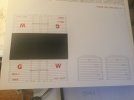
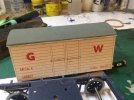
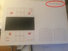
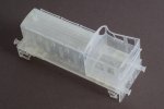
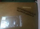
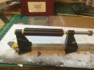
and printed v2 of the Mica. Well, it’s probably v7 or something, but anyway. The approach has changed somewhat as I made the W irons open at the bottom so the boxes can slide in, the springs will hold them in, and I’ll generate some plates to close them. The plate that joins the solebars together is also new. This allows me assemble the buffer planks with the buffers and coupling and a piano wire spring, Peco/Webster’s style, between them, before sticking it to the ends of the solebars. The W irons are now separate from the solebars, and fit on over a couple of spigots. Needed a touch with the scalpel around the holes for a lovely snug fit.

I printed the plate flat on the build plate of the printer, which predictably caused an elephant’s foot, and because I hadn’t thought about it, it was a bit of a pain to get off the plate, but it came out flat. I might try the same approach on the solebars, with adjustments for the foot, unfortunately, I don’t think it’ll work on the buffer planks which didn’t come out right. Some work needed there, and the T stanchions need to be a few thou thicker.

Annoyingly, I broke the handle on one brake lever, but managed to stick it back on. I’ll make it a wee bit thicker and hope it doesn’t show. The brakes themselves came out nicely, and fitted without any effort. I’ve no idea what went wrong with the Vac cylinder as I’ve done them before, but it was so bad it went straight in the bin.

The brake cross shaft was too tight a fit, so I’ll need to have a look at that too.

View attachment 182861
The axleboxes slide nicely in the W irons, and I think with a little work, they will also work with the Parkside kit too, as I still have one of them to build.

progress!
Simon
Looks good.
May I ask if the U channel of the under frame is to scale thickness. If not what thickness have you gone for?
 

simond

Western Thunderer
Thanks.

I have cheated….

the visible parts are scale thickness, so the flanges, etc. The rivet dimensions are guesstimated, and hopefully they are about right. Things like the brake levers, and V hangers are at or marginally over scale thickness along the visible (normally top) edge and very considerably over at the less visible edge, with a chamfer between. This for strength & stiffness obviously.

And of course there are lumpy bits in various locations to locate and connect to other non scale components, and there is a structure, hopefully well hidden, behind the axlebox to provide the suspension.

I’m sure it would be entirely possible to model and 3DP an RCH underframe, pretty much dead to scale, and once assembled, I’d expect it to be reasonably robust, at least the chassis itself, but it wouldn’t be a layout model, and you’d need to be a bit careful with the components during assembly as they’d be hyper-delicate, but in effect I’ve created my own kit, with the advantage of suspension.

And coupled with the printed card overlay on an MDF core, preprinted lettering, no transfers, assembly is pretty quick, and following a dose of Matt varnish, weathering can differentiate vehicles. I think it’s a viable method of building a train of the same vehicles, and it’s obviously cheaper than buying Parkside kits.

atb
Simon
 

Tony Overton

Western Thunderer
View attachment 182861
The axleboxes slide nicely in the W irons, and I think with a little work, they will also work with the Parkside kit too, as I still have one of them to build.

progress!
Simon
Simon
Certainly looking good and a different approach to wagon under frames. Can I ask, which GW wagon axle box drawing (the number) did you consult for your oil axle boxes?
Cheers
Tony
 

simond

Western Thunderer
Tony,

thanks, I had to think for a moment…

My model is drawn from figure 13 on page 46 of ABT, the “bible” for GW Wagons. It’s marked “OK F” though I didn’t do that on my model.

If you saw my v1 version at Kettering, it had the wrong (RCH) boxes installed.

atb
Simon
 

simond

Western Thunderer
One step forward…

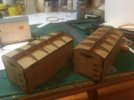
I have been trying to find a way of getting the roof to work, and hit on the idea of making the card overlay a single piece for both sides and the roof, wrapped over the top from solebar to solebar. This required some careful measurement of the three-centre roof and adjustment of the print file to suit, and I ran a couple of prints off on Thursday.

image.jpg

After a fight with the laser (it always seems to struggle on the first run, perhaps the belts are too cold & stiff or something, but it looses registration) I ran off a few of the revised inner body and put them together.

image.jpg

I think it worked, but still needs adjustment, the print is about a millimetre shy overall, probably to do with the quite tight rad over the cant rail. The gutter line is an overlay of styrene rod. Still needs the steps and door hardware adding, but I think this approach shows potential.

image.jpg

and a step back,

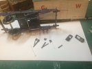
I dropped the chassis, from maybe 8 or 10 inches above, onto the workbench, and noticed that the brake lever loop had broken, “bah!”, I said, and then words of a far more foul and disrespectful kind when I realised that the W iron had also shattered.

image.jpg

This is frustrating, as it’s clearly going to be an issue if wagons disassemble themselves as a result of trivial mishaps, which are obviously going to happen from time to time.

I guess this takes us back to @adrian ’s comments about using brass etch for at least some components.
Post in thread 'SimonD’s workbench'
SimonD’s workbench

It would certainly be possible to make the W irons in brass with 3DP axleboxes, solebars, bufferbeams & brake assemblies. Perhaps the brake levers and their loops would also be better in brass.

Of course, this adds cost and delay to the mini-project too. Meanwhile, I’ll use the suspension approach, which seems to work very well, for the remaining Parkside kit that I have, and smugly note that my axleboxes are better than theirs!

Summary - the experiment was a success, but the result was a failure. :(
 
Last edited:

Rob R

Western Thunderer
Simon,
Maybe some experimentation with a different resin? (Just for the W Irons and Brake Gear?).
There are more flexible types out there.
Anycubic Tough is supposed to be a flexible enough to allow W Irons etc to be prised apart for wheel insertion (I have a bottle on the shelf but haven't opened it yet!), there will be others.
Would gluing the spring to the W Iron beef it up a bit as well? Or printing them as one piece?
You may well be able to thicken up the W Iron a fair bit as well without it being too obvious.
Too soon to give up yet...

Rob
 

simond

Western Thunderer
Thanks Rob,

maybe it could be made in a different resin. maybe I should buy something to try….

bit of a downer having it shatter like that, the previous versions have survived so far, but then again, I haven’t dropped them! I was lucky that a scalpel blade was sufficient to break the superglue that held the W iron onto the solebar, so printing another W iron will enable me recover that chassis.

The W irons are braced with hidden fillets and stiffeners, and have, do far, been strong enough. I think it was a brittle failure, the material (Siraya Fast Navy Grey) seems to be surprisingly flexible, and tough, but might be brittle under shock conditions.

OTOH, doing an etch isn’t rocket science (ironically, I’ve done them for work, never for models!) and I need some hinge straps and bases and the catwalk supports for the locoshed, so a few W irons wouldn’t be too challenging, provided I could make it all from the same thickness.

no modelling tomorrow. Time to think…
 

Richard Gawler

Western Thunderer
. . .

bit of a downer having it shatter like that, the previous versions have survived so far, but then again, I haven’t dropped them! I was lucky that a scalpel blade was sufficient to break the superglue that held the W iron onto the solebar, so printing another W iron will enable me recover that chassis.

. . .

Simon, I have had disapointments too. I bought a loco body through a designer on Shapeways and the result was extremely brittle. A bit like an egg shell really, and when I tried to open up the space for the motor the whole print shattered into many pieces. Not to be put off, I bought a different loco body, this one printed by the designer. Excellent detail in this one. Put it aside for a while in a safe place, away from dust and the cat but I suppose eight or ten inches about the central heating pipe in the floor void below . . .

DSCF2275.jpeg

From an entrepreneur who was a guest on Desert Island Discs, "There is no such thing as failure. Failure is success work in progress". As an engineer with control over the design and the ability to choose the resin, I think you have every possibility of success - don't give up :)
 
Last edited:

simond

Western Thunderer
Thanks Richard,

There are aphorisms about fixing what one can and not worrying about what one can’t, and having the wisdom to know the difference. Same is true here. I’m not yet sure whether I’m foolishly & stubbornly flogging a dead horse, or doggedly pursuing a holy grail in spite of setbacks... Wisdom in short supply!

At this point, I’m of the opinion that a more flexible resin might be worth a go. The design is such that the W irons can easily be etched, or 3DP, or possibly lasered from Trotec or similar (with minor mods) , so all is far from lost.
 

simond

Western Thunderer
Ran the printer last night with some curious results.

One of the cylinders was obviously not sufficiently well supported, despite being a mirror of the other, supports included, and it was found, firmly adhered to the FEP this morning. It appears that there have been a couple of glitches as well, two of the axlebox rear parts have failed completely and a third partially failed at the same height (again, cloned) as one another, but not the same layer as the cylinder, and the drum for the goods shed crane has printed most lop-sided, not at all sure how that happened.

But conversely, a significant number of parts printed perfectly, right through the suspect layers

image.jpg
if everything had been at the same height, one might conclude it was a glitch on the mains, or the cat leaping onto the printer, or something, but there seems no rhyme or reason to it.

Never mind, I have enough successes to try my axleboxes on the Parkside chassis, and to fix the chassis I dropped.
 

Pencarrow

Western Thunderer
Ran the printer last night with some curious results.

One of the cylinders was obviously not sufficiently well supported, despite being a mirror of the other, supports included, and it was found, firmly adhered to the FEP this morning. It appears that there have been a couple of glitches as well, two of the axlebox rear parts have failed completely and a third partially failed at the same height (again, cloned) as one another, but not the same layer as the cylinder, and the drum for the goods shed crane has printed most lop-sided, not at all sure how that happened.

But conversely, a significant number of parts printed perfectly, right through the suspect layers

View attachment 183498
if everything had been at the same height, one might conclude it was a glitch on the mains, or the cat leaping onto the printer, or something, but there seems no rhyme or reason to it.

Never mind, I have enough successes to try my axleboxes on the Parkside chassis, and to fix the chassis I dropped.
Cylinder top left looks most interesting...
 

simond

Western Thunderer
Fitted my 3DP axleboxes to the Parkside wagon. Need to print some spring supports for the guitar wire springs. Bit fiddly, but should be ok.

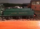
then returned to lathes and brass, turned up six top hat bushes to make bearings for Tony’s Manor tender.

1679953915522.jpeg

The CAD was done last week for the loco frames, they’ll get laser cut from Perspex tomorrow and sent off to Billy at Premier, so another loco in his catalog, and Tony’s conversion of the scratchbuilt second hand loco to Finescale will be able to proceed. I think it’ll turn out rather nicely.
 

Big Train James

Western Thunderer
Simon,
A common approach to the issue of the brittle nature of the ABS like resins is to mix in a percentage of flexible resin. Using a flexible resin by itself will almost certainly not yield the results you seek, as it's not known to attain the same level of surface finish or precision as the ABS like or other engineering resins.

I have seen references to mixing the Siraya Tech Tenacious with the Fast. It would require some further exploration to confirm the ratio, but I vaguely recall something about a 90/10 split. An example of parts printed with such a mixture (meaning the two types of resin, not the specific ratio) include operating HO scale knuckle couplers. I don't believe they would survive without some degree of added flexibility. I have considered experimenting with a resin mix, but haven't gotten around to it yet.

I have a similar story about dropping a printed model. I have done a hood for my switcher project, all printed in Fast Navy Grey. I was showing it off to other modelers at the Chicago show, and inadvertently dropped it. The shell exploded in a rather dramatic fashion. Of course the hood doors were just tacked into the carcass with white glue, meant to come back out, so they all popped out without any hesitation. The carcass itself also broke in multiple pieces or places. Gasps were heard around the room, several people fainted on the spot. :eek: I laughed it off though, because as I said at the time, I can just print another one.

I fully appreciate the allure of 3d printing parts versus etching. The parts are there in a matter of hours, and editing can happen right away. However, I also recognize that there are parts where thin sections are required simultaneously with increased strength, and 3d printing may not be the answer for those things no matter what we wish for.

If you try the resin mix, I'd love to hear about your results.

Jim
 

simond

Western Thunderer
Thanks Jim,

yes, the “just print another” aspect is appealing. W irons already done!

I'm interested by the concept of mixing resins, but wary in equal measure. There are some who will mix two tubes of paint, and produce perfection, but I’ll typically end up with a muddy mess. And annoyingly, it’ll be a different muddy mess to last time. Perhaps I ought to put on my methodology hat, but it feels too much like work then…

I'm surprised there isn’t a “tough, stiff-but-not-brittle, highly-superdetail” resin available. I guess my take on that is that if they knew how to blend it, and that we’d all pay an extra couple of quid per litre for it, they would probably sell it!

I’ll have a bit of a Google and see what I find. Thanks for the “heads up”.

cheers
Simon
 

Boyblunder

Western Thunderer
Simon, I had a similar experience a couple of weeks ago with a mix of items of which some printed fine and others failed. It happened after a previous total failure caused by the mains figure of 8 power lead coming loose from the power supply which in turn caused a confusing intermittent fault. This time there was no obvious explanation for the failures so I changed the FEP, let the cabinet temperature reach 23°c for longer before starting the print and then it worked fine.

I have found the same problem as others with the fragility of Fast Navy Grey so tried Siraya Tech Build Smokey Black which looked tougher according to the data sheets, sadly not noticeably stronger for fine detail parts such as David Rayner's GER crane jib and details not as good as Fast Navy Grey. Jim's resin mixing suggestion is interesting, Siraya Tech's own website suggests it is a thing "Tenacious can be printed on LCD and DLP printers and works great either by itself or mixed with other 405nm UV resin." As a design engineer you may have a better understanding of the data sheets in relation to shatter resistance than I do.
Robin
 

Big Train James

Western Thunderer
I need to correct something in my last post. I suggested mixing Fast and Tenacious, which is certainly doable. But I was really thinking about Siraya Tech Blu, as that's what I had seen discussed on another model train forum. I also need to correct the ratio I mentioned above, it appears to be a much higher ratio of the flexible resin to the Fast.

[edit] After some extra reading this morning, the ratios are all over the place from 90/10 to 50/50. But 90/10 to 80/20 mixes seem pretty common.

I've looked at the specs for both the Tenacious and the Blu. It's sort of difficult to get an apples to apples comparison of their respective mechanical properties since Siraya Tech doesn't appear to have a standard format for all resins. Some descriptions thoroughly define properties, hardness, shrink, flexibility, etc. Other specifications mention only some of the properties, or different ones than listed elsewhere. So I've never quite figured out which one of the two resins I should attempt to add into the base resin. Hadn't gotten around to a deeper dive yet.

I'm surprised there isn’t a “tough, stiff-but-not-brittle, highly-superdetail” resin available. I guess my take on that is that if they knew how to blend it, and that we’d all pay an extra couple of quid per litre for it, they would probably sell it!
Simon, I suspect that our goals with 3d printing are fairly distinct from the goals of most other users. High precision, high quality surface finishes, with prototypical thin cross sections seems less common, than the mini's or chunky functional parts most often seen in review and tutorial videos. Perhaps the ultimate resin hasn't been offered yet because vendors haven't yet identified our market, or there just aren't enough of us to make it worthwhile. If we could just get Siraya Tech to offer that perfect resin, while simultaneously getting Elegoo to mass produce a Mars 3T or Saturn 2T with existing build plate dimensions but twice the Z axis height, we railroad modelers would be all set. I'm still idly dreaming about a hack to my Mars 3 to replace the ball screw and a new, taller Z axis column. I'll get around to that right after I get done testing the mixed resins.:oops:

Jim
 
Last edited:
Signal box interior & lever frame

simond

Western Thunderer
Having painted myself figuratively into a corner with the Parkside version, and have disappointed myself with the home-brew versions, I decided to put the Micas on ice (heh heh) for a while.

I can’t progress with Tony’s Manor until I get the frames, so that’s parked in a siding.

Jon Fitness kindly sent me one of his lever frame kits which I’ll use in the back-dated Larry Goddard signal box. As there isn’t a trackplan yet, I’ll have to guess the lever colours. I believe Jon’s kit is for an LMS-derived BR standard box, but frankly, if you can tell that the frame is not 100% Reading through the windows, your nose is probably too damn close!

So what d’you get?

image.jpg

A fret of 20 levers, lever plates, back plates and a fold-up jig to support the levers whilst you solder the plates on, together with 21 rather oddly shaped laser cut bits to form the frame, two dowels, a pivot wire and an A4 instruction sheet.

Required; glue, solder, yellow, red, blue, black, white paint.

(and maybe some other colours, depending - I just saw a photo including a bright green lever - that’s new one on me)

the dowels are bamboo skewers, one of mine was a little loose so I purloined one from the kitchen and used it after sanding slightly.

image.jpg

Frame glued

First lever plate soldered. I had a PFI moment, but luckily found the plate on the floor under the bench…. The plates are very small, and it’s difficult. I didn’t get on with Jon’s jig, so made a holder for the lever from a bit of nice close-grained wood.

image.jpg

The levers are really nice, by using half etch on both sides of the fret, it’s got a very convincing pull-rod from the catch handle.

The difficult bit is the lower end of the lever plate, which is where the tag joins. At about the 7mm mark in this photo. Need to hold this bit whilst filing out the end of the etched groove so the plate sits nicely on the lever

image.jpg

I have a pair of slide pliers which get a firm grip, and the last couple of teeth on a razor saw do the needful.

set up for soldering:

image.jpg

The first three took a while but once I’d got the knack, the remaining 17 took a couple of minutes each. I used citric acid flux and as little solder as I could. Washed off with a toothbrush and hot water. It all assembles very simply, and I think it looks brilliant. I’ll strip it and paint it over the weekend. And cut a hole in the signal box floor to fit it.

image.jpg

The camera is cruel. A couple of the plates will need to be adjusted. Not going to lose any sleep over that!

I reckon it’s a fiddly build but well worth it.

atb
Simon
 

michael mott

Western Thunderer
That looks great, sometimes I wish I was back in the UK so as to have easier access to this kind of material.
Michael
 
Top